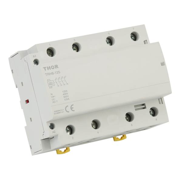
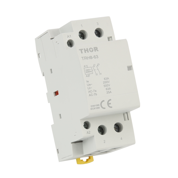
A contactor is made up of a coil, contacts, iron core, spring, and casing. Copper wire, with a resistivity of 1.68x10^-8 Ω·m, is usually used for 220V or 380V systems in various coils. When energized, the coil creates a magnetic field. Contact materials such as silver cadmium oxide have an electrical life expectancy of up to 100,000 cycles and current capacities ranging from 10A to 100A. The iron core is made of silicon steel sheets and operates in less than 0.1 seconds. Springs are generally fabricated from 65Mn steel and have a return force in the range of about 5N to 20N. The IP protection classes of the casings range from IP20 to IP65. Other elements include contact protectors, auxiliary contacts, and mechanical locking devices.
Main Components
When powered, the coil creates a magnetic field that pulls on the iron core. The most common types are AC coils, followed by DC coils. AC coils are used for 50/60Hz power systems, such as DIN43650A; DC coils match the same mounting as general AC coils and are suitable for low voltage systems (24VDC-48VDC), such as TM15-D coils, which feature a space-saving design providing wire terminations along one side of the coil winding. A coil typically uses copper or aluminum wire. Copper wire has a resistivity of 1.68x10^-8 Ω·m, while aluminum has a resistivity of 2.82x10^-8 Ω·m, making copper wire better for high-efficiency applications. For example, a conventional AC contactor coil has a resistance of around 50Ω, whereas the same DC coil can have an impedance in excess of 200Ω.
Contacts can be normally open or normally closed. Normally open contacts are open when the relay is de-energized and close when energized. Contact materials often use silver alloys (typically AgCdO or AgNi) to provide good conductivity and resistance to welding. AgCdO contacts can prevent welding under high current break conditions and have a long electrical life greater than 100,000 cycles. Contact current capacities may range from 10A to 100A, with commonly used ones including DIN-rail mount sizes with two or four poles for industrial automation.

When energized, the magnetic field causes movement in the iron core, actuating the contacts. The design must ensure operation within 0.1 seconds for prompt connection and disconnection in most circuits. The iron core is mainly made of high magnetic permeability silicon steel sheets, with a saturation flux density typically around 1.5T. Ni-Fe alloys, soft magnetic materials with a saturation flux density of up to 2T, are suitable for higher frequency switching operations.
Springs ensure that contacts reset instantly when the coil is de-energized. There should be a return force of 5N-20N depending on the contact. Micro contactor springs usually have a return force around 10N, while larger contactor springs can have forces up to 20N to guarantee stable contact reset. Springs are typically made from 65Mn steel or stainless steel, ensuring consistent performance over more than one million operations. For example, 65Mn steel springs have a tensile strength of 600MPa at room temperature, suitable for long-term high-frequency use.
The casing protects internal components from dust and moisture, with IP protection levels ranging from IP20 to IP65. For instance, contactors used indoors may have an IP20 rating to prevent finger access, while those used outdoors or in humid environments may have an IP65 rating to prevent dust and water spray ingress. Casings are usually made of high-strength engineering plastics like PA66 or metal materials like aluminum alloy. PA66 has a tensile strength of 80MPa, suitable for high-strength and insulation applications. Aluminum alloy casings have excellent heat dissipation performance, often used in high-power contactors, such as those in motor control systems exceeding 100A.
Auxiliary Components
Contact protectors prevent damage to contacts from arcs. Common types include RC circuit protectors and varistor protectors. RC circuit protectors are suitable for suppressing arcs in the range of 50V to 500V. For example, RC protectors used in household appliance contactors are typically designed for 100V to 240V, while industrial equipment RC protectors may be designed for 400V to 500V. Varistor protectors can withstand higher voltages, such as those used in high-voltage substation contactors, with design voltages up to 1000V. A standard RC circuit protector might have a resistance between 10Ω and 1kΩ and a capacitance between 0.1μF and 1μF to effectively absorb high-frequency arc energy during breaking.
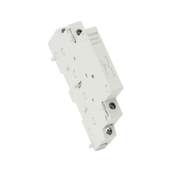
Auxiliary contacts provide additional switching functions, such as signal feedback. Each set of auxiliary contacts typically has a current capacity of 5A, suitable for control and signal circuits. In automation control systems, auxiliary contacts are commonly used for PLC (programmable logic controller) input signals, typically designed for voltages of 24V to 220V to provide accurate status feedback. The lifespan of auxiliary contacts can generally reach 500,000 operations to ensure long-term reliability. For example, some Siemens contactor auxiliary contact modules can provide up to 10A current capacity to meet higher control requirements.

Mechanical locking devices prevent misoperation. Their design must ensure no significant wear after 1,000 operations, commonly used in critical equipment control circuits. For example, in elevator control systems, mechanical locking devices prevent contactors from accidentally disconnecting during elevator operation. Mechanical locking devices are usually made of high-strength metals such as stainless steel or chrome-vanadium steel, with a tensile strength of over 1,000MPa to ensure structural integrity under high stress. A typical mechanical locking device might need to withstand an operating force of 10N to 50N and work normally in temperatures ranging from -40°C to +85°C to ensure reliability under various conditions.
Maintenance and Care
Common faults include contact welding, coil burnout, and iron core sticking. Contact welding is usually caused by overload current and is resolved by checking and adjusting the load current. For example, if the contact's rated current is 32A but the actual load current exceeds 40A, welding may occur; a clamp meter should be used to measure the load current and make adjustments. Coil burnout is often due to unstable voltage; the solution is to check the power supply voltage. For example, a 220V coil is easily damaged if the voltage fluctuates beyond 10% (i.e., 198V to 242V); a multimeter should be used to check the stability of the power supply voltage. Iron core sticking is mostly due to dust accumulation; the solution is to regularly clean the iron core to ensure flexible operation. Iron core cleaning can use compressed air and anhydrous alcohol every three months to ensure normal operation.
Monthly inspections should check for oxidation and erosion on the contact surface. If black oxide or significant erosion marks are found, sandpaper (usually 600# fine sandpaper) should be used to polish the contacts to ensure good performance. Quarterly, coil resistance should be measured to ensure it is within the rated range. For example, a standard 32A contactor coil resistance should be around 50Ω; if the measured result deviates from this range by more than 10%, the coil may have issues and should be considered for replacement.

Annually, all moving parts should be lubricated to ensure flexibility. Lubrication should use appropriate oils or greases, such as high-temperature lithium-based grease, ensuring excess lubricant is removed to prevent dust accumulation. Specific operation steps include: first, clean the moving parts, apply a small amount of grease with a cloth, and evenly spread it on the iron core and spring parts.
Regular maintenance is key to ensuring the long life and reliable operation of contactors. For high-frequency contactors (e.g., those operating more than 100 times per hour), comprehensive inspection and maintenance every six months is recommended. For normal frequency contactors (e.g., those operating fewer than 20 times per day), annual maintenance is sufficient to ensure normal operation.
Selection and Installation
Selection must consider the contactor's voltage level, current capacity, and control method. For example, contactors for household appliances typically have voltage levels of 220V or 110V, while those for industrial equipment commonly have voltage levels of 380V or 660V. In terms of current capacity, household appliance contactors generally range from 10A to 40A, such as the 25A contactors commonly used in air conditioning systems, while industrial equipment contactors may need up to 100A or more, such as the 150A contactors used in large motor control systems.
Control methods include manual and electric control. Manual contactors are suitable for simple circuit control, such as lighting switches in home circuits, while electric control contactors are suitable for complex automated systems, such as PLC-controlled production lines. The coil voltage range for electric control contactors can be 24V, 48V, 110V, 220V, etc., with the specific selection based on the control power supply voltage. For example, 24V coils are suitable for low-voltage control systems, ensuring operational safety.
Installation steps must ensure secure wiring to avoid loosening. For example, when installing a 25A contactor, appropriate copper wire specifications (e.g., 4 square millimeters) should be used, and the appropriate screw torque (usually 2.5Nm to 3.5Nm) should ensure secure connections. In practice, a torque screwdriver can ensure consistent tightness of each terminal, avoiding faults caused by poor contact.
Strictly follow the product manual to ensure vertical installation for proper operation. For example, most contactors require an installation tilt angle of no more than 5 degrees to ensure the normal movement of the iron core and contacts. After installation, power-on testing should ensure normal contact operation with no abnormal noise or heating. For example, an infrared thermometer can be used to detect the working temperature of the contactor, which should not exceed the ambient temperature by more than 30°C; if abnormal heating is found, further checks of the installation and wiring are necessary.
Attention should also be paid to the contactor's cooling and ventilation. In high-current applications, such as controlling high-power devices above 100A, the contactor's cooling performance is crucial. Ensure adequate cooling space around the contactor (typically at least 5 centimeters) and avoid direct sunlight or proximity to other heat sources. If necessary, cooling fins or fans can be added to enhance cooling.
In environments with strong electromagnetic interference, selection should consider the contactor's interference resistance. Specifically, choose contactors with shielding functions or install electromagnetic shielding materials (such as galvanized steel plates) around the contactor to prevent external electromagnetic interference from affecting normal operation.
