The main difference between grounding and bonding is their purpose for working. Safe discharge of fault currents to the ground and protection against electric shock incidents by connecting electrical systems or equipment to the earth is called grounding. The ideal grounding resistance as per the NEC is less than 25 ohms. This process connects various conductive portions with one another so that they then set the same voltage, which helps to prevent arcing from happening in areas of differing potential. Grounding involves running ground conductors and electrodes, while bonding joins equipment enclosures and metal structures together using specific dedicated bonds.
Definition and Purpose of Grounding
It is accomplished by connecting the metal parts to the neutral wire along with the grounding system. The main purpose is to provide a pathway with low impedance so that during an electrical fault condition, the excess current can safely return to the ground, preventing equipment damage or injury. In the U.S., these requirements are set out in NEC Article 250, which covers grounding systems and provides guidance on items such as types of grounding electrodes, conductors to be used with them, and maximum acceptable resistance between a ground electrode system and earth.
The National Electrical Code specifies that the resistance of the grounding system must not exceed 25 ohms, but this can vary depending on regional applications. More stringent or lenient rules may apply in high-reliability installations such as data centers. Lower grounding resistance enables fault currents to flow rapidly into the earth, thus preventing unnecessary damage to equipment.
Definition and Purpose of Bonding
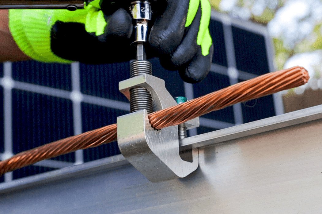
In order to ensure that all components are at the same potential, bonding connects two or more electrical conductors, equipment enclosures, or metal parts using wires (bonding jumpers). Differences in potential can cause arcing, overheating, short circuits, or electric shock. This makes bonding essential to maintain electrical safety by ensuring that the current returns to the source safely in the event of a fault. Earth bonding means that if an electrical fault occurs, the current will travel along a designated bonding path, preventing equipment enclosures or conductive parts from becoming energized, creating a safety hazard.
The NEC mandates that bonding systems create a system whereby electrical continuity is maintained between components. The conductors used for bonding are usually constructed of copper, aluminum, or other materials that provide an adequate path to maintain this continuity. Sufficient mechanical strength and corrosion resistance are required at connection points. Metal conduits, equipment enclosures, and structural steel may require bonding to equalize potential and prevent hazards.

Difference Between Grounding and Bonding
Grounding, on the other hand, provides a low-impedance path for current, which, in case of electrical faults, enables fault currents to pass harmlessly into the ground. This prevents disasters like current overload or short-circuit failures, protecting equipment from damage and reducing the risk of fire or electrical accidents. Grounding is usually applied to system neutral wires and equipment enclosures (metal) directly involved in the current flow, ensuring that fault currents do not travel through unintended paths.
The goal of bonding is to reduce the potential difference between conductive parts. When bonding is used, all components that are connected are at the same electrical potential, preventing hazards from voltage differences. Bonding also relates closely to the mechanical connection and long-term stability of metal parts, not just conductivity. For example, in electrical equipment installations, the metal enclosure of a distribution box must be bonded to the ground wire to ensure it does not become energized due to potential differences during a fault.
Technical standards and requirements
The design and installation of grounding and bonding in the U.S. are heavily regulated by the NEC. Materials and methods used to ground electrical systems are defined in NEC Article 250. Grounding systems can be built using metal water pipes, ground rods, or plates, as specified in the NEC.
Bonding of all non-current-carrying metal parts, such as equipment enclosures and support structures, is required to create a unified potential system. NEC 250.96 specifies that conductive parts that establish a ground-fault path must be bonded, regardless of the specific materials involved.
Difference in practical application
Grounding and bonding frequently operate together in the field. In a building, for instance, the neutral wire of the electrical system and the metal enclosure of distribution panels would be grounded, while all metal support structures, conduits, and equipment enclosures are bonded together. Grounding helps current return to the source with lower impedance, and bonding ensures that all metal surfaces are at the same potential, preventing electrical accidents caused by potential differences.
Grounding and bonding design becomes more complex in certain applications, like data centers or facilities with high electromagnetic interference. In data centers, equipment often requires lower grounding resistance, and bonding not only eliminates potential differences but also improves electromagnetic shielding to reduce high-frequency EMI affecting the equipment.