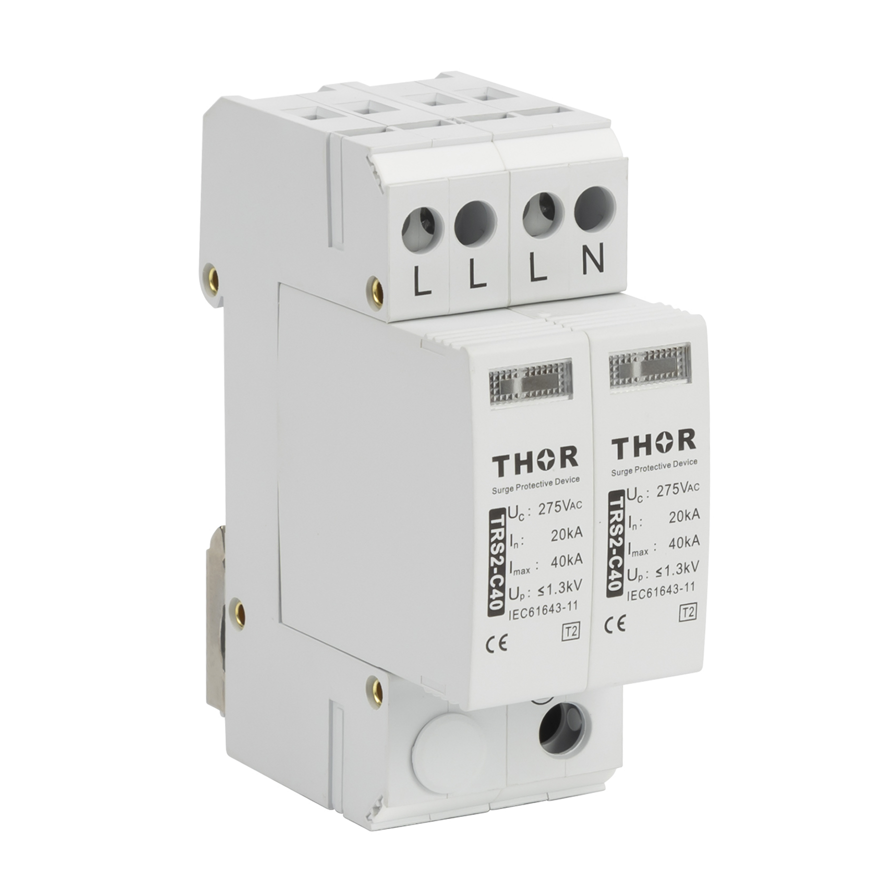
The working principle of surge protection device:
The surge arresters commonly defined as SPDs (Surge Protection Devices), are devices designed to protect electric systems and equipment against transient and impulse overvoltages such as those caused by lightning strikes and by electric switching.
Their function is to divert the discharge or impulse current generated by an overvoltage to earth/ground, thereby protecting the equipment downstream.
SPDs are installed in parallel with the electric line to be protected. At the mains rated voltage, they are comparable to an open circuit and have a high impedance at their ends.
In the presence of an overvoltage, this impedance falls to very low values, closing the circuit to earth/ground.
Once the overvoltage has ended, their impedance rises again rapidly to the initial value (very high), returning to open loop conditions.
The Type 2 SPD is the main protection system for all low voltage electrical installations. Installed in each electrical switchboard, it prevents the spread of overvoltages in the electrical installations and protects the loads.
Type 2 surge protective devices (SPDs) are designed to protect electric installations and sensitive equipment against indirect surges and ensuring a low protection level (Up).
Type 2 surge protective devices provide effective protection against these dynamic disturbance variables. Whether in an industrial environment or in a residential building, type 2 protection ensures basic protection for your installations and devices.

